Posts

Bluetooth car

Image
Hello guys... To make Bluetooth robot you need         parts                                                                                     buy links Arduino Uno (any arduino works)                                 https://amzn.to/2MUYONt Bluetooth modules                                                        https://amzn.to/2AyfN5t l298N motor driver module                                            https://amzn....

Mosquito bat circuit

Image
hello guys..!! Today we will reverse engineering of mosquito bat. This mosquito bat can generate 2000v to 4000v so be careful. It can harm you. Do not touch circuit during operation.  here is the  circuit diagram here is how this circuit works:   The joule thief concept is used in this circuit, wherein only a single NPN transistor and a center-tapped transformer execute sustainable oscillation across the two winding of the transformer. This part if circuit converts the low direct voltage to high alternating voltage. There is high frequency transformer is used. Working frequency of transformer is around 1KHz to 200KHz. After that voltage multiplayer circuit is used. In our case it is voltage trippler circuit. So the output will be approx three times the peak input voltage.This is how mosquito bat circuit works.  here is the charging circuit diagram  :- THANK YOU for watching.

SIM800L GSM/GPRS Module interface with Arduino

Image
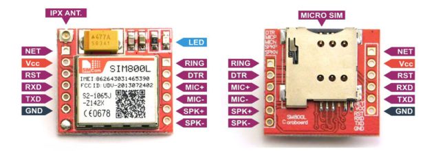
HELLO guys SIM800L gsm/gprs module is 2G gsm module. Working voltage range is 3.7v to 4.2v. Use 3.3 logic level. here is the pins of module :- What you need:----                     parts                                                                    buy links   Arduino uno                                                            https://amzn.to/3gPxePi    sim800l gsm/gprs module                                        https://amzn.to/3duMA9U breadboard      ...

AC DIMMER

Image
Hello friends.... here is the schematic diagram of simple basic ac dimmer. thank you for watching YouTube channel --- subscribe now https://www.youtube.com/channel/UCY6KA8oFk1s36fyPiFEmedQ/?sub_confirmation=1

Binary Clock

Image
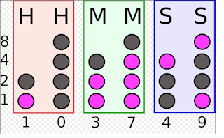
Hello friends..... here is how you can read binary clock ... here you can see 1,2,4,8 assigned for column. in the picture you can see in HH section first column first led is on so it is one,second column all led is off so 0 SO HERE HOUR IS 10. Now in MM section two led is on so add the assigned numbers. in picture add (1+2=3) and add(1+2+4=7) SO MINUTE IS 37. Then second (SS)  is 49. what you need....                     components                                                                           buy link  Arduino pro mini (you can use any arduino)                              https://amzn.to/2X7O8Qh ftdi programmer       ...