SIM800L GSM/GPRS Module interface with Arduino
HELLO guys
SIM800L gsm/gprs module is 2G gsm module. Working voltage range is 3.7v to 4.2v.
Use 3.3 logic level.
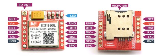
here is the pins of module :-
 What you need:----
parts buy links
here is the schematic diagram
 code for AT commands ------------------------------------------------------------------------
/*
* er bros
* sim800l test 1
* at commands
* YouTube :- https://www.youtube.com/channel/UCY6KA8oFk1s36fyPiFEmedQ
*/
#include <SoftwareSerial.h>
SoftwareSerial Sim800l(13,12); // sim800l tx and rx
void setup() {
// put your setup code here, to run once:
Serial.begin(9600);
Sim800l.begin(9600);
}
void loop() {
while(Sim800l.available()){
Serial.write(Sim800l.read());
}
while(Serial.available()){
Sim800l.write(Serial.read());
}
}
------------------------------------------------------------------------------------------------------------
AT commands
SIM800L gsm/gprs module is 2G gsm module. Working voltage range is 3.7v to 4.2v.
Use 3.3 logic level.
here is the pins of module :-

parts buy links
- Arduino uno https://amzn.to/3gPxePi
- sim800l gsm/gprs module https://amzn.to/3duMA9U
- breadboard https://amzn.to/304tIdO
- 1K resistor
- 2K resistor
- buck converter for powring up gsm module https://amzn.to/3gM2zCl
- some jumper wires https://amzn.to/2XRJ6rk
here is the schematic diagram

/*
* er bros
* sim800l test 1
* at commands
* YouTube :- https://www.youtube.com/channel/UCY6KA8oFk1s36fyPiFEmedQ
*/
#include <SoftwareSerial.h>
SoftwareSerial Sim800l(13,12); // sim800l tx and rx
void setup() {
// put your setup code here, to run once:
Serial.begin(9600);
Sim800l.begin(9600);
}
void loop() {
while(Sim800l.available()){
Serial.write(Sim800l.read());
}
while(Serial.available()){
Sim800l.write(Serial.read());
}
}
------------------------------------------------------------------------------------------------------------
AT commands
- AT :- for test
- ATI :- for product info.
- AT+GMI :- for manufacturer identification
- AT+GSN :- for IMEI number
- AT+CSQ : for signal quality response between 0-31, 31 is the best.
for more command click here
sms sending from arduino code :-----------------------------------------------------------------------------
/*
* er bros lab
*/
#include <SoftwareSerial.h>
//Create software serial object to communicate with SIM800L
SoftwareSerial mySerial(13, 12); //SIM800L Tx & Rx //tx-13, rx-12 pins
void setup()
{
//Begin serial communication with Arduino and Arduino IDE (Serial Monitor)
Serial.begin(9600);
//Begin serial communication with Arduino and SIM800L
mySerial.begin(9600);
Serial.println("Initializing...");
delay(1000);
mySerial.println("AT");
updateSerial();
mySerial.println("AT+CMGF=1"); // Configuring TEXT mode
updateSerial();
mySerial.println("AT+CMGS=\"+CCxxxxxxxxxx\"");//change CC with country code and xxxxxxxxxxx with phone number to sms
updateSerial();
mySerial.print("TEST SMS SEND GSM800L"); //text content
updateSerial();
mySerial.write(26);
}
void loop()
{
}
void updateSerial()
{
delay(500);
while (Serial.available())
{
mySerial.write(Serial.read());//Forward what Serial received to Software Serial Port
}
while(mySerial.available())
{
Serial.write(mySerial.read());//Forward what Software Serial received to Serial Port
}
}
--------------------------------------------------------------------------------------------------------------------------
and for appliance control
output pin is pin 9. connect led or relay module to pin 9.
here is the code
---------------------------------------------------------------------------------------------------------------------
/*
* er bros
*
* sms control
*/
#include <SoftwareSerial.h> // We include the Software Serial library
#define op 9
SoftwareSerial SIM800L (13, 12); // We instantiate the SIM800L object and pass it the parameters of the TX and RX pins
String sms; // Declare the variable of type String value.
void setup () {
pinMode (op, OUTPUT); // Declare pin as output
digitalWrite(op, LOW);
Serial.begin (9600); // We initialize the first Serial communication.
SIM800L.begin (9600); // We initialize the second Serial communication.
SIM800L.println ("AT + CMGF = 1"); // We will use SMS.
delay (100); // 0.1 sec delay
SIM800L.println ("AT + CNMI = 1,2,0,0,0"); // Set the SIM800L to show msm by com. Serie.
}
void loop () {
// Get it to show us what message comes through the serial monitor.
if (SIM800L.available ()) {
sms = SIM800L.readString (); // Save the sms received by the Arduino in the var value
Serial.println("New SMS: "+ sms); // Print that SMS on the Serial monitor
}
if (sms.indexOf ("ON")>=0){
digitalWrite (op, HIGH);
}
if(sms.indexOf ("OFF")>=0){
digitalWrite (op, LOW);
}
}
--------------------------------------------------------------------------------------------------------------------------
Thank you for watching

Can I use 3G and 4G sim for sim800l ??
ReplyDeleteBecause now a days 2G sims are not available.
you can use any sim card excluding JIO sim, because JIO have only 4G tower so there is no 2G or 3G signal available but if you use other sim for e.g airtel or bsnl that are start with 2G so that have 2G and 3G signals.
Delete