Posts

GESTURE control with arduino

Image
 HELLO guys. what we need :- Arduino uno apds-9960 Breadboard  Jumper wires here is the connection :- here is the code link :- https://github.com/vivek-chauhan7/APDS9960 here is the library :-  https://github.com/sparkfun/APDS-9960_RGB_and_Gesture_Sensor

seven segment display with arduino

Image
Hi ---------------------------------------------------------  here is the circuit diagram ---------------------------------------------------------- HERE is the code for without library -------------------------------------------------------------------------------------- /*  * ER BROS LAB  */ #define a 6 #define b 7 #define c 8 #define d 9 #define e 10 #define f 11 #define g 12 #define dp 13 void setup() {   pinMode(a, OUTPUT);   pinMode(b, OUTPUT);   pinMode(c, OUTPUT);   pinMode(d, OUTPUT);   pinMode(e, OUTPUT);   pinMode(f, OUTPUT);   pinMode(g, OUTPUT);   pinMode(dp, OUTPUT); } void n0() {   digitalWrite(a,LOW);   digitalWrite(b,LOW);   digitalWrite(c,LOW);   digitalWrite(d,LOW);   digitalWrite(e,LOW);   digitalWrite(f,LOW);   digitalWrite(g,HIGH);   digitalWrite(dp,HIGH); } void n1() {   digitalWrite(...

timer switch

Image
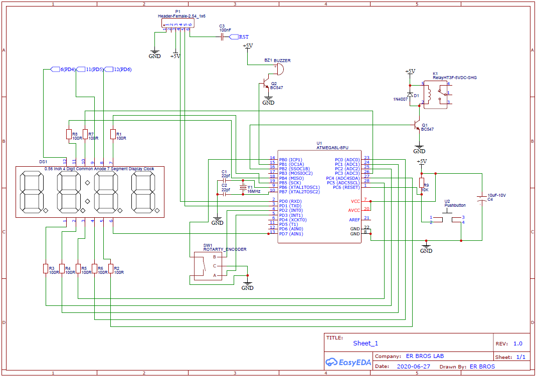
Hi here is the simple and very useful project. parts list ATMEGA8 (you can use atmrga328p, or any other arduino) - 1 22pf capacitor -2 16MHz crystal - 1 10K resistor - 1 100E resistors -8 push button - 1 rotary encoder with push button - 1 4 digit seven segment display - 1 relay- 1 bc547 transistor - 2 buzzer - 1 zero pcb - 1 10uf capacitor - 1 100nf capacitor - 1 some wires and male or female header pins here is the  schematic diagram here is the code link https://github.com/vivek-chauhan7/Timer-Switch YOUTUBE LINK https://www.youtube.com/channel/UCY6KA8oFk1s36fyPiFEmedQ

PIR sensor with and without arduino

Image
Hello guys here you can see how interface PIR sensor with and without arduino board. use of this sensor is very easy , by connecting some wires as shown in diagram you can use this sensor. here is circuit diagram :- After connection as per diagram you need to upload this simple code :- ---------------------------------------------------------------------------------------------------------------------------------------------------------------------------------------------------------------------------------------------------- #define pir 10 #define op 13 int val; void setup() {   pinMode(pir, INPUT);   pinMode(op, OUTPUT); } void loop() {   val = digitalRead(pir);   if(val == HIGH) {     digitalWrite(op, HIGH);   }   else {     digitalWrite(op, LOW);   } } -----------------------------------------------------------------------------------------------------------------------...

Simple Home Automation

Image
Hi This is the simplest home automation using HC-05 Bluetooth module. parts you need...              components                                                                                  buy link Arduino Uno (any arduino works)                                 https://amzn.to/2MUYONt Bluetooth module                                                           https://amzn.to/2AyfN5t Relay module                                ...

Bluetooth car

Image
Hello guys... To make Bluetooth robot you need         parts                                                                                     buy links Arduino Uno (any arduino works)                                 https://amzn.to/2MUYONt Bluetooth modules                                                        https://amzn.to/2AyfN5t l298N motor driver module                                            https://amzn....

Mosquito bat circuit

Image
hello guys..!! Today we will reverse engineering of mosquito bat. This mosquito bat can generate 2000v to 4000v so be careful. It can harm you. Do not touch circuit during operation.  here is the  circuit diagram here is how this circuit works:   The joule thief concept is used in this circuit, wherein only a single NPN transistor and a center-tapped transformer execute sustainable oscillation across the two winding of the transformer. This part if circuit converts the low direct voltage to high alternating voltage. There is high frequency transformer is used. Working frequency of transformer is around 1KHz to 200KHz. After that voltage multiplayer circuit is used. In our case it is voltage trippler circuit. So the output will be approx three times the peak input voltage.This is how mosquito bat circuit works.  here is the charging circuit diagram  :- THANK YOU for watching.